


Detalizēta detalizēta apakšzemes cauruļvadu galerijas saliekamo detaļu ražošanas procesu izstrāde
Pirmkārt, vietas norises
Saliekamā vieta
1. Vietne tiek izvēlēta atbilstoši faktiskajai projekta situācijai. Vietne pieņem slēgtu pārvaldību, lai izveidotu importu un eksportu, un celtniecības piebraucamais ceļš ir rezervēts teritorijas plānošanas apgabalā, un dažādās zīmes ir pakārts importam un eksportam saskaņā ar noteikumiem.
2. Ražošanas vietas izkārtojums ir stingri jāatbilst standarta rūpnīcas prasībām, jāatbilst arodveselības, drošības un vides vadības sistēmas prasībām un HSE ekspluatācijas instrukcijām, kā arī jāizveido dažādas drošības vides aizsardzības iekārtas. Tam jābūt pilnībā aprīkotam, lai apmierinātu drošas un civilizētas ražošanas prasības, notekūdeņu novadīšanu un atkritumu apglabāšanu. Stingri ievērojot vietējo pašvaldību departamentu attiecīgos noteikumus.
3. Notīriet saliekamo vietu, izlīdzinot, vibrējot un saspiežot, ieliekot 20cm biezu cementa stabilizētu apmetuma pamatni, izlīdzinot un vibrējot un saspiežot. Galvenais ceļu no rūpnīcas ielej 15cm biezu C20 komerciālu betonu uz cementa stabilizētas kaļķakmens bāzes. , uzstādīšanas zona, saliekamie materiāli, ražošanas zona, integrēta cauruļu galerija, dabas saglabāšanas izvietojuma zona, kas iepilda komerciālo betonu 10cmC20. Ziemeļu celtņa dzelzceļa montāžas pozīcijā rakšanas dziļums ir 60 cm, bet betonu ielej un novieto sliežu ceļu. Arī veiciet šīs trīs lietas:
(1) Vietu nepieciešams tīrīt un izlīdzināt, ieskaitot saliekamās vietnes, savienojot celtniecības jostas un esošos transporta ceļus, kā arī saliekamās vietās.
(2) Saliekamās vietās ir jānotīra akmeņi, nezāles, koki, struktūras u.tml., Kas ietekmē celtniecības tehnikas pārvietošanos vai celtniecības darbus, grāvai un grēdai jābūt izlīdzinātām, un zemie apgabali ar uzkrāto ūdeni jāiztukšo un vajadzības gadījumā jāaizpilda. Aizpildiet, pilnībā garantējiet zemes līdzenumu un nesošo un spiedes ietilpību.
(3) Lai novērstu vides piesārņojumu un augsnes eroziju, pirmsapstrādes vietas tīrīšana un izlīdzināšana jāveic, lai saglabātu zemes iegādi vai zemes aizņemšanu, satiksmes šķēršļus, ēku, objektu, pieminekļu utt. Bojājumus.
4. Tērauda stieņu apstrādes un uzstādīšanas zonas, iebūvētas cauruļu galerijas saliekamās ražošanas tvaika laukums, integrēta cauruļu galerijas dabas rezervāts, integrēta cauruļu galerijas uzglabāšanas vieta un citas funkcionālās zonas. Biroja platība un dzīvojamā platība ir atkarīga no faktiskās situācijas, un saliekamās lauka ieejas un izejas vietas ir izveidotas kā apsardzes istaba. Otrkārt, ražošanas process
Ražošanas procesa shēma
1. Būvmateriālu nostiprināšanas inženiertehniskie materiāli, paraugu ņemšanas pārbaude, tērauda apstrāde, tērauda stieņu iesiešana, uzstādīšana.
(1) Pastiprinājuma pieejas pārbaude a. Armatūra ir karsti velmēta HPB300 klases tērauda un karsti velmētas HRB400 kategorijas tērauda stieņi. Tērauda stieņa standarta stiprība atbilst GB50010-2010 4.2.2. Punkta prasībām. Rievota tērauda stieņa atbilst dzelzsbetona tēraudam: II daļa: karsti velmēti stieņi (GB1499.2-2007); Vieglie tērauda stieņi atbilst dzelzsbetona tērauda prasībām: I daļa: karsti velmēti stieņi ar stieņiem (GB1499.1-2008). Tērauda plāksne ir izgatavota no Q235-B tērauda, metināšanas elektrods HPB300 kategorijas tērauds ir metināts ar E43 tipa elektrodu un HRB400 kategorijas tērauds tiek metināts ar E55 tipa elektrodu. b. Pirms tērauda nonāk vietā, pārbaudiet šķirni, šķirni, specifikāciju, daudzumu un materiālu sarakstu, stingri ievērojot prasības, vai produkta kvalitātes sertifikāts, rūpnīcas pārbaudes ziņojums un atkārtotas pārbaudes ziņojums ir pilnīgi un derīgi. Mehānisko īpašību pārbaudei jāatbilst attiecīgajiem standartiem. c. Pirms tērauda iekļūšana laukā un pirms lietošanas pārbauda tērauda stieņa izskata kvalitāti neatkarīgi no tā, vai tā ir taisna, nav bojājumu, sārņi nav iekļauti virsmā, smagā āda, plaisas, eļļas traipi, granulas vai sārtā rūsa, vienāda krāsa , skatiet tērauda stieņa diametru. Ievērojiet prasības, lai neietekmētu tērauda stiprību un stiprinājumu. Tērauda plāksnes, metināšanas stieņi utt. Tiek pārbaudītas pirms tērauda stieņu pārbaudes posteņiem pirms ieiešanas vietā.
(2) tērauda stieņu glabāšana a. Tērauda stieņi, kas nonāk vietā, tiek uzglabāti tērauda stieņu uzglabāšanas zonā atbilstoši šķirnei, specifikācijai un kategorijai. Materiālus uzglabā materiālais personāls un turētāji. Lai izvairītos no rūsas, tērauda stienis jāpārklāj ar spilventiņu. b. Pārbaudiet, vai tērauda stienim ir rūpnīcas sertifikāts un rūpnīcas pārbaudes ziņojums un pārbaužu ziņojums. Pārbaudiet izskata kvalitāti un apjoma reprezentatīvo diametru. Tērauda stienis ir jāpārbauda visaptveroši, ņemot vērā tā kvalitātes indeksu. Saskaņā ar partijas pārbaudi diametrs un svara novirze ir tādi paši kā tajā pašā rūpnīcā, tajā pašā krāsns skaitā, tajā pašā specifikācijā, tajā pašā ražošanas procesā, un 60 tonnu tērauda stieņi, kas tajā pašā būvlaukumā tiek ievadīti tajā pašā laikā, ir inspekcijas partija, kas ir mazāka par 60 tonnām. Tāpat kā testa partija veic paraugu ņemšanu. Tērauda stieņu paraugu ņemšanu veic vadošais inženieris. Trīs tērauda stieņus ņem, lai ņemtu divus stiepes testa paraugus, katrs ar garumu aptuveni 450 mm, un divus auksti saliektus testa paraugus, kuru garums ir aptuveni 350 mm, ievieto testa kastē, un pēc tam tiek kontrolēts blīvēšanai vai kontrolei testa zāle. Ja atkārtotas pārbaudes ziĦojuma rezultāts ir bez kvalifikācijas, to veic divreiz un atkārtoti pārbauda. Pārskatīšanas ziņojuma rezultātus kvalificē, un profesionālās uzraudzības inspektors paraksta apstiprinājumu, un pārstrādes procesā var izmantot tērauda stieņu partiju. Citu materiālu glabāšanu un uzglabāšanu veic, izmantojot mitruma izolāciju.
(3) Armatūras apstrāde Pirms apstrādes saskaņā ar konstrukcijas specifikācijām, garumu un daudzumu, kombinējot ar dažādām apstrādes metodēm, katras armatūras garumu nosaka aprēķins, lai nodrošinātu precizitāti. Apstrādes laikā pārbaudiet, vai sagatavošanas tabulā ir kļūda vai izlaidums. Pārbaudiet materiālu tabulu katram tērauda stieņa veidam. Pēc šīm divām pārbaudēm nospiediet materiālu tabulu, lai atbrīvotu reālo paraugu. Pēc tam, kad izmēģinājuma produkcija ir kvalificēta, to var apstrādāt partijās. Labi tērauda stieņi būtu kārtīgi un kārtīgi sakrauti. Tērauda stieņa virsmai jābūt tīrai, un pirms izmantošanas jānotīra tauki, netīrumi un rūsa. Tērauda stieņi ir iztaisnoti un mehāniski iztaisnoti. Tērauda stienim pēc iztaisnošanas nav lokālu lieces, mirušo līkumu vai nelielu viļņu. Tērauda stieņu griešana pamatojas uz tērauda stieņu skaitu, diametru, garumu un daudzumu. Tērauda stieņa garums un garums ir jāsadala, un vispirms ir jāsadala īsais materiāls, un īsā tērauda galva pēc iespējas jāsamazina un jāsamazina, lai taupītu tēraudu un samazinātu zaudējumus. Kad tērauda stienis ir saliekts, loks nosaka lejas punktu un nosaka lieces leņķi, pamatojoties uz katra tērauda stieņa atsitiena stiprumu. Pirms formālas locīšanas tērauda stieņi, kas ir izliekti lielos daudzumos, tiks pakļauti izmēģinājumu saliekšanai, un attiecīgie tehniskie dati tiks noteikti pirms partijas lieces. Kad tērauda stieņi ir saliekti, loka forma veido loka. Pēc saliekuma lielums nav lielāks par izmēru. Jāņem vērā lieces korekcijas vērtība. Izliektā tērauda stieņa lieces diametrs D un vidējās daļas izliekums ir vismaz 5 reizes lielāks par tērauda stieņa diametru. Tērauda stieņa garums ir jāapskata vispusīgi atkarībā no detaļas lieluma, aizsargkārta biezuma un tērauda stieņa locīšanas korekcijas vērtības. Tērauda stieņu apstrādes pieļaujamā novirze nedrīkst pārsniegt specifikāciju. Tērauda stienim ar nepietiekamu gatavo materiālu tiek izmantota locītavas locītavas spiediena metināšanas metode. Stieņu metinātājam jābūt apmācītam speciālā metinājuma metināšanas procesā un pārbaudei ņemt paraugus. Pēc tam, kad ir izveidoti dažādi tērauda stieņi, pieļaujamā novirze nedrīkst pārsniegt specifikāciju: spēka ribu pilns garums ir ± 10 mm; stiegru katras daļas garuma novirze ir ± 5 mm; izliektu ribu novirze ir ± 20 mm no locekļa, liels tilpums Betons ir ± 30 mm; tērauda stūra novirze ir 3 mm; 6-12 mm apaļa riba tiek ievietota statīvā, un gala āķa garums ir 75 - 105 mm saskaņā ar galvenās ribas diametru. Konkrētais aprēķins pirms balināšanas tiek noteikts, apstrādāti tērauda stieņi tiek klasificēti un uzglabāti, un veidotos tērauda stieņus uzglabāšanas un transportēšanas laikā nevar deformēt.
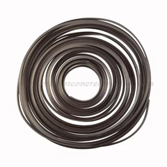
Pītas karkass (pastiprināta tērauda) tērauda veidne
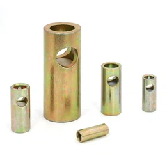
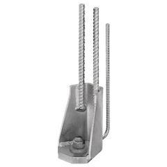
Grūtības: grūtības izdarīt galveno taisnstūra augšējās caurules ribas ir ārējā ribas galvenā ritenī. Katrs gredzens sastāv no četriem tērauda stieņiem ar diviem lokiem, no kuriem katrs veido taisnstūra virskārta armatūras gredzenu. Loka rādiuss ir pārāk mazs, izliektais loka segmentu ir īss un precizitāte ir augsta. . Risinājums: pirms tērauda stieņi ir saliekti, atzīmējiet tos katras loka krustojumā. Tad R90 grādu loka leņķis ir izliekts ar trīs leņķi, un taisnā daļa nav saliekta. Pēc tam, kad loka liekums ir pilnībā izliekts, to ievieto standarta galvenajā pārbaudē. Pēc tam, kad prasības ir izpildītas, kustīgā riteņa kustības vietas zīme tiek veikta liekšanas mašīnu darbības platformā nākamajai ātrai ražošanai. Trīskriemeļu locīšanas iekārtai ir jābūt aktivizētai un pretējā virzienā. (4) Tērauda stieņu metināšana Izveidotais tērauda stienis tiek novietots uz tērauda stieņu metināšanas darba instrumenta saskaņā ar metināšanas konstrukcijas rasējumiem. Metināšanas kvalitāte ir svarīga sastāvdaļa, lai nodrošinātu tērauda stieņa kopējo stiprību. Tērauda stieņu pārstrādes rūpnīcā tērauda stieņus galvenokārt attīra, veicot dubultās plakanas metināšanas, lai notīrītu stobrās noberžus un gala virsmas rūsas, eļļas traipus un oksīda plēvi pirms metināšanas, un metāla spīdums tiek sasmalcināts, un nav oksidēšanas parādības. Tajā pašā laikā tērauda stieņa gala virsma ir jāsamontē, lai atvieglotu labu kombināciju. Abām pusēm piestiprinātie ķermeņi ir jāsaskaņo, lai pārliecinātos, ka abi tērauda stieņi atrodas vienā un tajā pašā asī, un abu tērauda stieņu lokālais attālums nav lielāks par 3 mm. Metināšanas laikā veiktajam spiedienam jābūt vienmērīgam un stipram, un temperatūra jāpārrauga 30-40 MPa atkarībā no tērauda stieņa diametra, lai panāktu labu saķeri starp abiem tērauda stieņiem. Ja dažāda diametra tērauda stieņi ir sametināti, novirze nedrīkst pārsniegt 7 mm. Mērapulksteņi un vietas metināšana ir stingri saskaņā ar noteikumiem, un metināšanas personāls ir sertificēts darbam. Pēc tam, kad metināšana ir pabeigta, savienojums tiks mainīts no balta uz melnu, lai atbrīvotu skavu, un tērauda stieni izvelk raiti, lai izvairītos no saliekuma. Pēc tam, kad ir pabeigta tērauda stieņu metināšana, metināto šuvju izskatu pārbauda laikus, un savienojumus, kas neizdodas vizuāli pārbaudīt, atkārtoti sametina. Visiem metināšanas operatoriem ir jānodrošina, lai visi metināšanas mehānismu tipi būtu labā darba stāvoklī, savlaicīgi apgūtu dažādu metināšanas mehānismu galvenos raksturlielumus un parametrus un izvēlētos labākos parametrus faktiskajai darbībai saskaņā ar parastā metāla apstākļiem un laika apstākļiem, lai nodrošinātu metināšanas kvalitāte. . (5) Pastiprinātas tērauda sprosti ir jāpārkalibrē pirms specifikācijas, izmēra, formas, daudzuma, pozicionēšanas instrumentu utt., Un jāveic visaptveroša pārbaude saskaņā ar konstrukcijas rasējumiem un sastāvdaļu sarakstu. Dizainu, sastāvdaļu sarakstu un fizisko objektu var saskaņot. Drošība. Pirms sistēmas uzstādīšanas pastiprinājums ir novietots uz pozicionēšanas instrumentu platformas saskaņā ar konstrukcijas datiem. Tajā pašā laikā, saskaņā ar atrašanās vietu, nosaka stāvēšanas pastiprinājuma iestatījumu, lai nodrošinātu, ka tērauda stieņi pēc uzstādīšanas atbilst prasībām. Drošības procesā tērauda stieņus galvenokārt izgatavo ar stiepļu savienošanu un lokšņu metināšanu. Caurumi ir izgatavoti no 20 ~ 22 # stieples. Saistīšanas un saistīšanas metode atbilst specifikācijām un noteikumiem. Vietas metināšana galvenokārt tiek izmantota, lai veidotu tērauda stieņus un stieņus. Fiksācijai, lokšņu metināšanai jābūt stingrai, punktiem jābūt vienmērīgi sadalītai, un spēka ribām nedrīkst nopietni bojāt. Tērauda stieņa stiprinājuma savienojums atbilst šādām prasībām: a. Apļa garuma beigas ir vismaz 10 reizes lielākas par tērauda stieņa diametru tērauda stieņa saliektajā daļā, un savienojumu nedrīkst novietot pie komponenta maksimālā lieces momenta. b. Spriegošanas zonā I-veida tērauda nostiprināšanas savienojuma galu ievieto āķī. Tajā pašā sadaļā spriegošanas zonas locītavas šķērsgriezuma laukums ir mazāks par 50% no spēka pieņemšanas kopnes kopējās platības, un stiprinājuma savienojums nedrīkst būt lielāks par 50%. Tajā pašā laikā ne vairāk kā 25% sastiprināšanas šuves nedrīkst pārsniegt 50% saspiešanas zonā. c. Pastiprināti savienojumi, piestiprināti pie stieples centrā un abos galos. d. Spriego ribu kopīgās pozīcijas ir nobīdītas viens no otra. Spriegotu tērauda stiegrotu savienojumu kājas garumam jāatbilst konstrukcijas prasībām. Metināmie tērauda šuves un mehāniskie savienojumi jāievieto minimālajā lieces momentā un jānogriež. e. Ja spriegotā tērauda stieņa diametrs ir ≥ 25 mm, nav ieteicams izmantot nesavietotu savienotājuzmavu. f Birstoša tērauda stieņa betona aizsargkārta biezumam jāatbilst konstrukcijas prasībām. Lai nodrošinātu tērauda stieņa pareizo novietojumu, tas ir piesaistīts un uzstādīts atbilstoši konstrukcijas prasībām. g. Armējošā būru saistīšanas procesā viena ΦPVC caurule ir iepriekš apglabāta uz četrām savienojuma pusēm, Φ14mm, PVC caurules garums tiek noteikts atbilstoši savienojuma mutes sieniņu biezumam un iepriekš iebūvētajam PVC caurule tiek izmantota kā pārbaudes caurums un injekcijas caurums. Pacelšanas caurumi ir uzstādīti 500 mm virs un zem centrālās ass integrētās cauruļu galerijas kreisās un labās puses. Divas Φ125 * 10mm * 220mm tērauda caurules tiek metinātas uz tērauda rāmi, un Φ140 * 4 tērauda plāksne tiek izmantota blīvēšanai. Pirms celšanas ir uzstādīta Φ125 * 10mm * 180mm tērauda caurule. Φ110mm * 350mm dzelzs tapa tiek izmantota kā integrēta caurules pakaramais auss, lai apmierinātu integrētās cauruļu galerijas celšanas konstrukciju. Pastiprināti tērauda darbi ir slēpti projekti. Pirms betonu iepildīšanas tērauda stieņi un iegultās detaļas jāpārbauda un jāapstiprina, kā arī jāsaglabā slēptie tehniskie dati. Pēc tam, kad būvuzraudzības inženieri piekrīt, var veikt nākamo procesu.
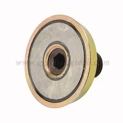
Tērauda veidņu montāža
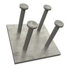
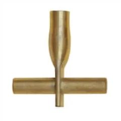
Visefektīvākā montāžas procesa metode ir: pirmkārt, jāatbalsta iekšējā pelējuma, tērauda apkakles savienojuma ribas vispirms ir jāsavieno, un pēc tam jāuzliek apakšējā veidnē, un pēc tērauda apšuvuma tērauda gredzenu savienojošās rievas rāmis ir ievietots pelē, un tērauda stieņi ir metinātas. Pēc tam, kad skelets ir ievietots pelē, tiek iepildīts ieplūdes caurums, ieplūdes atvere un iepriekš iebūvēta tērauda plāksne. Pēc metināšanas, ārējā veidne ir samontēta. Lai nepieļautu, ka pacelšanas urbums ir neprecīzs, pacelšanas caurums ir piestiprināts pie ārējās formas, un ārējā veidne ir salikta, un pēc tam metināšanas kontaktdakša ir iepriekš sagatavota. Apglabāts tērauda gredzens. (6) Armētais aizsargslānis Aizsargājamais betona slānis ir izgatavots no betona bloka, biezums ir vienāds ar projektētā aizsargājošā slāņa biezumu, bloka lielums ir 3 cm × 3 cm, spilvenu skaits ir lielāks par C25 javas stiprību un Izgatavošanas laikā konsistence tiek pastiprināta, lai sasniegtu dizaina izturību. 85% no iepriekšminētajiem var tikt izmantoti. Izmantojot vertikālajā struktūrā, blokā var tikt apglabāta 20 # saistošā līnija, un bloks ir piestiprināts pie tērauda stieņa ar vadu. Apakšējās plāksnes apakšējais slānis un sienas armatūras slānis ir novietots uz vienu kvadrātmetru uz kvadrātmetru, un tiek izvietoti plūmju ziedi. Spilventiņu atstatums ir pareizi šifrēts. Saprātīgi sakārtojiet blokus un stingri piesiet tos uz strāvas tērauda stieņiem, nevis novietot uz necaurlaidīgām cīpslām, lai stiprinājumi būtu izturīgi, lai izvairītos no pārvietošanās un slīdēšanas lūšanas procesā; vai bloki ir pilnībā pārbaudīti pirms betona liešanas Trūkst vai bojāti. 2. Betona liešana (1) Betona materiāli Betona transportēšana uz saliekamo vietu notiek ar betona tankkuģi un tiek piegādāta noliktavā ar betona sūkņa kravas automobiļa palīdzību. Betona slīpums parasti tiek kontrolēts no 140 līdz 180 mm (īpašā vērtība ir atkarīga no dienas temperatūras). 4 betona vibrācijas stieņi ar vibrējošu rādiusu 20-25 cm, tāpēc atstatums starp katru stieni ir 40 cm. Katrs stieņa dziļums ir 5 cm zemāk par iepriekšējo vibrējošo virsmu, un vibrācijas laiks stienim ir 2-3 minūtes. (2) Sajaukšanas attiecības projektēšana un pārbaude a. Maisīšanas koeficienta konstrukcija Lai izpildītu betona konstrukcijas izturības prasības, salizturību, necaurlaidību, smilšu agregāta izplešanās ātrumu un konstrukcijas darbspēju, betona konstrukciju maisījuma proporcijas optimizācijas testu, tajā pašā laikā tā atbilst būvniecības ūdens cementa attiecības un krītošanas prasībām, un to pārskata un apstiprina uzraudzības inspektors. Betona sajaukuma proporcijai jānodrošina, ka iegūtais betons var atbilst konkrētajiem liešanas apstākļiem, un ūdens patēriņš betona maisījuma proporcijā ir pēc iespējas mazāks. b. Betona maisījuma attiecības testu betona maisījuma attiecības pārbaudes plāns, ieskaitot betona maisījuma attiecības testu un betona veiktspējas testu ar dažādām stiprības pakāpēm, jaukuma attiecības tests 14d pirms dažāda maisījuma attiecības testa sastāvdaļām un sajaukšana, molding un uzturēšana utt Maisījuma koeficienta pārbaudes plāns tiek ziņots uzraudzības inženierim. c. Celtniecības maisījumu attiecības kontrole Saskaņā ar maisījuma attiecības testu un uzraudzības inženiera apstiprināto partiju sarakstu, betona maisījuma attiecība tiek kontrolēta, un kopējais ūdens patēriņš tiek pielāgots atkarībā no kopējā ūdens satura. Betona slīpumu nosaka strukturālās daļas raksturs, stiegrojuma ātrums, betona transportēšanas un liešanas metode un klimatiskie apstākļi, un, cik vien iespējams, tiek izmantots neliels kritums. Betona slīpums atbilst prasībām SL677-2014. (3) Betona paraugu ņemšanas tests Betona liešanas procesa laikā darbuzņēmējs veic atlaišanas atveres un iepildīšanas vietā betona paraugu ņemšanas testu saskaņā ar SL352-2006 noteikumiem un uzraudzības iestādes norādījumiem un iesniedz uzraudzības iestādei šādus materiālus : a. Un tā integrētās cauruļu galerijas kvalitātes sertifikāts; b. Testa parauga sastāvs, sajaukšana un izmēri; c. Testa parauga sagatavošanas un apkopes apraksts; d. Testa rezultāti un apraksts; e. Dažāda vecuma betons. Testa dati, piemēram, tilpuma blīvums, spiedes izturība, stiepes izturība, maksimālā stiepes vērtība, elastības modulis, Puasona attiecība, slīpums, sākotnējais iestatījums un galīgais iestatīšanas laiks. (4) Betona liešana a. Komerciālā betona maisījuma attiecībai jāatbilst DL / T5330-2005 prasībām "Hidraulisko betonu maisīšanas koeficienta konstrukcijas specifikācija", un pēc galīgās iestatīšanas izmantojiet cementa un ūdens reducēšanas līdzekli ar relatīvi agru sākotnējo iestatīšanas laiku un agru stiprības pieaugumu. Dažādām piedevām, tādām kā gaisa ievilkšanas līdzeklis un agrās izturības līdzeklis, jāņem vērā betona transportēšanas lielie attālumi, betona agrīnas stiprības paaugstināšana, betona mazināšanas laika samazināšana, būvniecības perioda saīsināšana un īpaši jāatrisina betona izturības lēns pieaugums ziemas būvniecībā . Problēma ar vietnes betona slīpumu jāpārbauda 140-180 mm. b. Kad pelējuma un tērauda stieņi ir uzstādīti un kvalificēti tehniķiem kvalitātes kontrolei un uzraudzībai, un apstiprina, var iepildīt integrēto cauruļu galeriju. Atveres augstums ir 2 m vai vairāk virs zemes, un piliens ir 2 m vai mazāk. Mīkstais stobra muciņš ir uzstādīts pie mutes, lai nodrošinātu, ka betona krišanas augstums ir mazāks par 2 m. c. Betona cauruļvadu tuneļa betons pieņem simetrisko liešanas metodi, lai ņemtu vērā, ka malas augstums nedrīkst pārsniegt 40 cm, un konstrukcijai ar nepārtrauktas liešanas metodi nedrīkst būt intermitējoša. d. Betons tiek ielej slāņos, noteiktā virzienā un ar noteiktu biezumu. Betons ir horizontāli slāņots un slāņa biezums ir 30-40 cm. e. Vibrējošais izmanto spraudkontaktu vibrējošo stieni, kustības attālums nepārsniedz 1,5 reizes vibrācijas joslas darbības rādiusu un atstāj 5 līdz 10 cm attālumu no sānu formas. Vibrācijas laikā ievietojiet apakšējo betona slāni 5 līdz 10 cm, un pēc katras vibrācijas lēnām jāpiedāvā vibrācijas josla. Izvairieties vibrēt veidni, tērauda stieņus utt. Vibrācijas laikā; katrai vibrācijas daļai tas ir jāaktivizē, līdz betons tiek saspiests, tas ir, betona pārsegi grimst, nav redzami burbuļi, un virsma ir plakana un dubļaina. Ieliešanas procesa laikā katram darba veidam jābūt sakārtotam, lai pārbaudītu tērauda stieņu, kronšteinu un trafaretu izmaiņas, un situācijai vajadzētu tikt galā ar laiku. 3, lodziņu caurulīšu uzturēšana un demontēšana
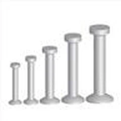
Kārbas caurule saliekama
(1) Pēc tam, kad betons tiek iepildīts, pēc tam, kad betons ir sākotnēji uzstādīts, iebūvētā cauruļu galerija tiek tvaicēta augstā temperatūrā. Tvaicējot, tiek izmantots pielāgots tvaicēšanas pārsegs un integrētā cauruļu galerijas veidne ir pārklāta ar tvaicēšanas pārsegu un tvaicēšanas vāka apakšdaļa ir noslēgta, lai tvaicēšanas procesa laikā tvaiks netiktu izlādēts. Tvaicējamais katls tiek tvaicēts videi draudzīgas tvaicēšanas iekārtas. atbalsts. Tvaicēšanas procesā tas ir sadalīts četrās pakāpēs: statiskā pārtraukšana, sasilšana, pastāvīga temperatūra un dzesēšana. Statiskās apstājas laikā apkārtējā temperatūra jāuzglabā zem 5 ° C, un temperatūras paaugstināšanās jāpārbauda 15 ° C / h laikā. Pastāvīgā temperatūra: kad temperatūra sasniedz 60 ° C, tvaicēšanu var pārtraukt pēc četru stundu ilgas pastāvīgas temperatūras tvaicēšanas. Dzesēšana. Integrētās cauruļu galerijas dzesēšanas ātrums tvaicētā nojume ir mazāks par 10 ° C / h, un integrētās cauruļu galerijas virsmas temperatūra nav lielāka par 5 ° C, lai integrēto cauruļu galeriju varētu noņemt no tvaicēts vāks. Tvaicēšanas procesa laikā speciāls personāls ir izveidots tā, lai efektīvi kontrolētu temperatūras paaugstināšanos un kritumu un detalizēti reģistrētu. Pirmkārt, pēc tam, kad integrētā cauruļu galerija tika ieleta un apturēta 2 stundas, sākotnēji tika uzstādīta integrētā cauruļu galerija, un pārbaudē nebija noviržu. Tvaicēšanas vāks un aprīkojums tiek pārvietoti uz saliekamo ražošanas zonu, un integrētā cauruļu galerija ir izveidota ar tvaicēšanas pārsegu. Stingri noslēgts, pārbaudiet tvaicēšanas iekārtu un tvaicēšanas vāka blīvēšanas stāvokli un notīriet tvaicēšanas iekārtu. Pēc tam, kad visi preparāti ir uzstādīti, uzsāk tvaicēšanas iekārtu sildīšanu, un jāpievērš uzmanība, lai apkures procesa laikā kontrolētu sildīšanas ātrumu 15 ° C / h. . Ir aizliegts uzsildīt pārāk ātri vai pārāk lēni, kas ietekmēs integrētās cauruļu galerijas spiedes stiprību un veiktspēju. Kad temperatūra sasniedz 60 ° C, tiek sākta tvaicēšana nemainīgā temperatūrā. Pēc nemainīgas temperatūras, kas tvaicē četras stundas, tvaicēšanu var pārtraukt. Pēc nemainīgas temperatūras tvaicēšanas ir pabeigta tvaicēšanas kanāla atdzesēšana un uzturēšana, un dzesēšanas ātrums tiek stingri kontrolēts. 10 ° C / h temperatūrā temperatūra nokrīt uz integrētās cauruļu galerijas virsmas temperatūru un apkārtējā temperatūra nepārsniedz 5 ° C, tvaicēšanas vāku var noņemt un integrētā cauruļu galerija tiek nojaukta un pārvietota uz dabas saglabāšanu dabas rezervāts. (2) Pēc tvaicēšanas pabeigšanas cauruļu gala demontēšana un dabas aizsardzības līdzekļa uzturēšanas plāns sasniegs 50% no projekta stipruma, un temperatūras starpība starp tvaicēšanas vāka iekšpusi un ārpusi pēc apstājas nedrīkst būt lielāka par 5 ° C tvaicē vienu stundu. pelējums. Noņemšanas kārtība ir no iekšpuses uz augšu, no augšas uz leju. Demontāžas procesā tas jādara pakāpeniski, lai noņemtu pelējumu, saliekamo integrēto cauruļu galerija un apakšējā veidne no galddatora tiek noņemta no pastatņu celtņa un transportēta uz izraudzīto dabas aizsardzības ēku dabas laistīšana. Stingri aizliegts izmantot lentu, lai izspiest trafaretu zem parauga demostēšanas procesa laikā. Pēc tam, kad dabīgā tehniskā apkope sasniegs 75% no konstrukcijas izturības, integrētā cauruļu galerija tiks izņemta no dabas saglabāšanas novietnes, lai to atceltu. (3) Cauruļu gala nolocīšanas un novietošanas plāns Pēc tam, kad ir pabeigta betona iepildīšana, konstrukcijas izturība ir 50% un pēc tam, kad tvaicēšana tiek pārtraukta uz vienu stundu, temperatūras starpība starp tvaicējamā izlietnes iekšpusi un ārpusi nevar būt lielāka nekā 5 ° C, un pelējumu var nojaukt. Noņemšanas kārtība ir no iekšpuses uz augšu, no augšas uz leju. Demontāžas procesā tas jāsvītro pakāpeniski secīgi. Pēc tam, kad pelējums ir noņemts, saliekamo izstrādājumu un apakšējo veidni noformē no pelējuma un transportē uz noteikto dabas aizsardzības zonu dabīgai laistīšanai. Stingri aizliegts izmantot lentu, lai izspiest trafaretu zem parauga demostēšanas procesa laikā. Lentes vai stiepļu trošu kontakta leņķiskās daļas ir aizsargātas ar spilventiņu, kas ir viegls un viegls celšanas procesa laikā, un visas darbības vērš īpaša persona. Pēc tam, kad produkta izturība sasniedz 75% no izturības, produkts tiek pārnests uz gatavo dabas aizsardzības zonu. Transporta laikā pārvietojiet izstrādājumu no paplātes un pagrieziet produktu. Lai atvieglotu produkta uzglabāšanu, produkta sākotnējais produkts tiek pārvērsts grīdas apakšā, un produkta uzglabāšanas augstums ir divi slāņi. 4, slēgta ūdens testēšanas standarti
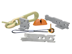
Slēgtā ūdens pārbaudes shēma
(1) Ūdens iesmidzināšana integrētajā cauruļu galā. Pirms ūdens iesūkšanas integrēto cauruļu gala bloku noslēdz un noslēdz. Pēc pārbaudes veikšanas ūdeni ievada integrētajā cauruļu galerijā. Ūdens injicē no integrētās cauruļu gala apakšējā gala. Pēc tam, kad ūdens ir piepildīts, integrētās cauruļu galerijas iekšējā siena un saskarnes materiāls ir pilnībā uzsūcas un iegremdēšanas laiks nav mazāks par specifikācijā norādīto garumu. (2) Pārbauda a. Pēc tam, kad visaptverošā caurules izlietne atbilst prasībām, testu veic. Testa galva ir 2 m virs integrētās cauruļu gala augšpuses. Ja augstums no ieplūdes integrētās cauruļu gala augšdaļas līdz pārbaudes vietai ir mazāks par 2 m, saskaņā ar pašvaldības inženierijas kvalitātes pārbaudes un pieņemšanas standartu "slēgtā ūdens testa ūdens līmenis urbumā, lai atbilstu būvniecības prasībām. b. Sāciet laiku, kad testa galva sasniedz noteiktu līmeni, novērojiet integrētās cauruļu galerijas noplūdi līdz novērošanas beigām. Šajā laikā ūdeni vajadzētu nepārtraukti piegādāt integrētajai cauruļu galvai, lai testa galva nemainītos, un ūdens izskalošanās laiks ir vismaz 30 minūtes. c. Aprēķina izmērīto ūdens noplūdi saskaņā ar šādu formulu: q = W / TL, kur q ir izmērītā ūdens izskalošanās [L / (min.m)]; W - ūdens daudzums (L); T - novērošanas laiks (min) L - testa caurules gala garums (m). c. Pēc integrētās cauruļu galerijas pabeigšanas termiņā paziņo trešo inspekcijas pusi un uz vietas noteikto kontroli, ko veic Puse, lai veiktu integrētās cauruļu galerijas sistēmas slēgto ūdens testu. Kad tests ir pabeigts, virsbūves būvniecības puse veic integrētās cauruļu gala tranšejas aizpildīšanu. (3) Pārbaudes punkti a. Integrētā cauruļu galerija ir jāpārbauda pēc sadaļas; b. Integrētās cauruļu galerijas un inspicēšanas urbuma izskats ir kvalificēts, un nav ūdens noplūdes un nopietnas ūdens noplūdes; c. Mērīšanas laiks pēc ūdens iepildīšanas integrētajā cauruļu galerijā Dzelzsbetona caurules iegremdēšanas laiks nedrīkst būt īsāks par specifikācijā norādīto garumu; d. Visaptverošu cauruļu galerijas noslēguma ūdens pārbaudi veic uz vietas, lai izmērītu faktisko summu un lauka aprēķinu, un aizpilda attiecīgās veidlapas kā slēpto pieņemšanas ierakstu. (4) Paziņojums par slēgta ūdens testēšanu Slēgtā ūdens sekcijas slēgtā daļa nav blīva, un tā bieži tiek atstāta novārtā, jo tā atrodas labi. Ja ķieģeļu sienu izmanto blīvēšanai, uzmanība jāpievērš šādiem punktiem: Pirms bloķēšanas sprausla ir 0,5. Tīriet caurules iekšējo sienu, kas atrodas diapazonā m, cementa biezenis ir nokrāsota un izmantotie ķieģeļi ir mitrās izmantošanai. Mūrēšanas javai jābūt ne mazākam kā M7.5 un labai konsistencijai. Cementa java savienošanai un apmetumam nav mazāka par M15. Ja caurules diametrs ir liels, iekšējai un ārējai malai jābūt mazai un jāizmanto tikai ārējā viena sāna savienojums vai virsma. Virsma jāuzklāj ūdensnecaurlaidīgā 5-slāņu veidošanas metodē. Ja apstākļi to atļauj, to pirms kvalitātes pārbaudīšanas var iegremdēt. Iepriekš iestatītais kanalizācijas caurums jāpārbauda caurules iekšējā daļā, lai to iztukšotu un testētu. (5) Ūdens caurplūdes apstrāde integrētā cauruļu galerijā Slēgtais ūdens tests ir visaptveroša integrētās cauruļu galerijas konstrukcijas pārbaude un materiālu kvalitāte. Noplūdes gadījumā vispirms ir jānorāda noplūdes un rūpīgi jāapstrādā pēc ūdens iztukšošanas integrētajā cauruļu galerijā. Pēc apstrādes tests atkārtojas, un process atkārtojas, līdz ūdens ir noslēgts. Treškārt, materiāla kvalitāte: 1, tērauds; stiepes izturība nav zemāka par HRB400 trīspakāpju vītņota tērauda vai karsti velmētu, auksti velmētu salātu tēraudu, tērauda īpašībām jāatbilst prasībām GB1499.2, GB13788, GB1499.1. 2, cements; vajadzētu izmantot portlandcements, parasto portlandcements, var izmantot arī sulfātam izturīgu porcelāna cementu, ātri cietējošu cementu. Cementa izturībai jāatbilst attiecīgi GB175 un GB748 prasībām. 3, agregāts; smalkas granulās būtu jāizmanto vidēja rupja smilts, smalkuma modulis 2.3 ~ 3.3, dubļu saturs nav lielāks par 2%; rupja granulāta maksimālais daļiņu izmērs nedrīkst pārsniegt 1/3 no dzelzsbetona kasti caurulītes sieniņu biezuma. Tas nedrīkst būt lielāks par 3/4 no apļveida armatūras stieņu neto attāluma, dubļu saturs ir ≤1%, akmens pulvera saturs ir ≤5%, adatu līdzīgo daļiņu saturs ir ≤10% un porainība ir ≤45%. 4. Piedevas un piemaisījumi; betons, ja tiek pievienoti piemaisījumi un piemaisījumi, var nelabvēlīgi neietekmēt lodziņu caurulītes. Jāievēro GB8076 noteikumi. Pievienojot nātrija un polikarboksilāta ūdens reducējošo vielu, pievienošanas daudzums jānosaka pēc testa; FDN-2 superplasticizera daudzums ir 0,75% ~ 1%. Polikarbonilskābju sērijas ūdens reducējošais līdzeklis jābalsta uz mātes aģents atšķaidīšanas daudzumu. 5. Ūdens: betona sajaukšanas ūdenim jāatbilst JGJ63 prasībām. 4. Iegremdrošināšanas standarta standarts: 1. Izskatu kvalitātes pārbaude ir šāda: (1) Kastes iekšējai un ārējai virsmai jābūt blīvai, gludai un tīrai, tai jābūt bez plaisām, kārbiņām, bojājumiem, porām, izlietnēm, pakļautām smiltīm, kas pakļautas akmeņi, ekspozīcijas mīkstums un lipīga āda. . (2) Gala kontaktligzdai jābūt tīrai un bez leņķiem. Plaisas, atklātās ribiņas utt. Nav blīvi saprotamas. Savienotāja līmlentes gropei jābūt gludai un gludai, graudi ir skaidri, un nav jāuzliek peldoša mīkstums un gruži. (3) Augšējā un apakšējā plāksnes iekšējai un ārējai virsmai jābūt plakanai un vietējai nevienmērīgai. (4) Sānu iebūvētajām skrūvēm jābūt stingrām, zīda ceļam jābūt vienmērīgam un kārtīgi sakārtotam. (5) Spriegojuma caurumam jābūt vienmērīgam, atvere ir konsekventa, un nav noviržu no šuvēm.
2, ražojuma izmēru novirze (1) tērauda rāmis: augstums ± 5 mm, garums ± 5 mm, platums ± 3 mm, pastiprināta stieņa ± 5 mm, tērauda stieņa diametrs ± 0,1 mm (2) lodziņa caurule: augstums ± 5 mm, garums ± 2 mm, platums ± 2 mm, kontaktligzdas dziļums ± 1 mm, ligzdas garums ± 1 mm, sienas biezums ± 1 mm. (3) Box culvert parameter concrete 28d compressive strength C45/, demoulding strength requirement reaches 20Mpa, impermeability When P6 is reached, the freezing and thawing reaches F100, the external pressure crack load reaches 85kn/m, and the failure load reaches 120kn/m. First, the venue settings
19e0885965a9620c7b4ea459ffc0934f.jpg
Prefabricated site
1. The site is selected according to the actual situation of the project. The site adopts closed management to set up import and export, and the construction access road is reserved in the site planning area, and various signs are hanged at the import and export according to regulations. 2. The layout of the prefabrication site shall be in strict accordance with the requirements of the standard factory, meet the requirements of occupational health and safety and environmental management system and HSE operation instructions, and set up various safety environment protection facilities. It shall be fully equipped to meet the requirements of safe and civilized production, sewage discharge and garbage disposal. Strictly in accordance with the relevant provisions of local government departments. 3. Clean the prefabricated site, leveling, vibrating and compacting, laying a 20cm thick cement stabilized macadam base, smoothing and vibrating and compacting. The main road of the plant will pour 15cm thick C20 commercial concrete on the cement stabilized macadam base. , installation area, prefabrication, production area, integrated pipe gallery natural conservation placement area pouring 10cmC20 commercial concrete. In the gantry crane rail erection position, the excavation depth is 60cm, and the concrete is poured and the track is laid. We must also do these three things: (1) The site needs to be cleaned and leveled, including prefabricated sites, connecting construction work belts and existing transportation roads, and passages in prefabricated sites. (2) In the prefabricated site, the stones, weeds, trees, structures, etc. that affect the passage or construction work of the construction machinery should be cleaned up, the ditch and the ridge should be leveled, and the low-lying areas with accumulated water should be drained and filled, if necessary, changed. Fill in, fully guarantee the flatness of the ground and the load-bearing and compressive capacity. (3) Pre-fabrication site cleaning and leveling shall be carried out to save land acquisition or land occupation, no traffic obstruction, no damage to buildings, facilities, monuments, etc., to prevent environmental pollution and soil erosion. 4. Prefabrication of the steel bar processing and installation area, integrated pipe gallery prefabrication production steaming area, integrated pipe gallery natural conservation shed, integrated pipe gallery storage area and other functional areas. The office area and living area are set according to the actual situation, and the prefabricated field entrance and exit is set up as a guard room. Second, the production process
Production process flow chart
1. Reinforcement engineering construction materials entering the site, sampling inspection, steel processing, steel bar binding, installation. (1) Reinforcement approach inspection a. Rebar is hot-rolled HPB300 grade steel and hot-rolled HRB400 grade steel bar. The standard strength of steel bar meets the requirements of 4.2.2 of GB50010-2010. The ribbed steel bar complies with the steel for reinforced concrete: Part II: Hot-rolled ribbed steel bars (GB1499.2-2007); light-round steel bars meet the requirements of steel for reinforced concrete: Part I: Hot-rolled ribbed steel bars (GB1499.1-2008). The steel plate is made of Q235-B steel, the welding electrode HPB300 grade steel is welded with E43 type electrode, and the HRB400 grade steel is welded with E55 type electrode. b. Before the steel enters the site, check the variety, grade, specification, quantity and material list in strict accordance with the requirements, whether the product quality certificate, the factory inspection report and the re-inspection report are complete and valid. The mechanical properties test must be in accordance with the relevant standards. c. Before the steel enters the field and before use, check the appearance quality of the steel bar, whether it is straight, no damage, no slag inclusion on the surface, heavy skin, crack, oil stain, granular or flake old rust, uniform color, view the diameter of the steel bar Meet the requirements, so as not to affect the strength of the steel and anchoring performance. Steel plates, welding rods, etc. are inspected with the steel bar inspection items before entering the site. (2) Storage of steel bars a. The steel bars entering the site are stored in the steel bar storage area according to the variety, specification and grade. The materials are stored by the material staff and the custodians. The steel bar is required to be covered with a pad to prevent rust. b. Check whether the steel bar has the factory certificate and the factory inspection report and the re-inspection report. Check the appearance quality and the volume representative diameter. The steel bar must be inspected comprehensively for its quality index. According to the batch inspection, the diameter and weight deviation are the same as the same factory, the same furnace number, the same specification, the same production process, and the 60-ton steel bar entering the same construction site at the same time is an inspection lot, less than 60 tons. Also as a test lot, carry out witnessed sampling. Sampling of steel bars shall be carried out by the supervising engineer. Two steel bars shall be taken to take two tensile test pieces, each with a length of about 450 mm, and two cold-bent test pieces with a length of about 350 mm, placed in the test box, and then supervised for sealing or monitoring the test room. If the result of the re-examination report is unqualified, it shall be double-sampled and re-tested. The results of the re-examination report shall be qualified, and the professional supervision engineer shall sign the approval, and the batch of steel bars may be used in processing. Storage and storage of other materials shall be carried out by means of moisture insulation. (3) Rebar processing Before processing, according to the design specifications and length and quantity, combined with different processing techniques, the length of each rebar is determined by calculation to ensure accuracy. During processing, check whether there is any error or omission in the blanking table. Check the material table for each type of steel bar. After these two inspections, press the material table to release the real sample. After the trial production is qualified, it can be processed in batches. Good steel bars should be stacked neatly and orderly. The surface of the steel bar should be clean, and the grease, dirt and rust must be cleaned before use. The steel bars are straightened and mechanically straightened. The steel bars after straightening shall not have local bending, dead bends or small waves. The steel bar cutting should be based on the steel bar number, diameter, length and quantity. The length and length of the steel bar should be broken and the short material should be broken first, and the short steel head should be reduced and shortened as much as possible to save steel and reduce loss. When the steel bar is bent, stake out determines the bending point and determines the bending angle based on the rebound strength of each steel bar. Before the formal bending, the steel bars that have been bent in large quantities will be subjected to trial bending and the relevant technical data will be determined before batch bending. After the steel bar is bent, the arc forms an arc. After the bending, the size is not larger than the blanking size. The bending adjustment value should be considered. The bending diameter D of the bent steel bar and the bend of the middle part is not less than 5 times the diameter of the steel bar. The length of the steel bar should be considered comprehensively according to the size of the component, the thickness of the protective layer, and the adjustment value of the bending of the steel bar. The allowable deviation of steel bar processing shall not exceed the specification. For steel bars with insufficient finished material, the butt joint pressure welding method is used to butt the foot length and then bend. The butt welder must be trained in a special butt welding process and sampled for inspection. After the various steel bars are formed, the allowable deviation shall not exceed the specification: the full length of the force ribs shall be ±10 mm; the deviation of the length of each part of the stirrups shall be ±5 mm; the deviation of the bent ribs shall be ±20 mm of the member, large volume The concrete is ±30mm; the deviation of the steel corner is 3mm; the 6~12mm round rib is made into the stirrup, and the length of the end hook is 75~105mm according to the diameter of the main rib. The specific calculation before the blanking is determined, the processed steel bars are classified and stored, and the formed steel bars are prevented from being deformed during storage and transportation.
Braided skeleton (reinforced steel) steel formwork
Difficulties: The difficulty in making the main ribs of the rectangular top pipe is the outer rib main rib. Each ring consists of four steel bars with two arcs each forming a rectangular top pipe rebar ring. The radius of the arc is too small, the curved arc segment is short, and the precision is high. . Solution: Before the steel bars are bent, mark them at the intersection of each arc. Then, the R90 degree arc is bent by three-roll bending, and the straight line segment is not bent. After the arc is fully bent, it is placed on the standard master inspection. After the requirements are met, the moving wheel movement position mark is made on the bending machine operating platform for the next quick production. The three-roll bending machine needs to have the function of jog and reverse. (4) Steel bar welding The formed steel bar is placed on the steel bar welding work tool according to the construction drawings for welding. The welding quality is an important part to ensure the overall strength of the steel bar. In the steel bar processing factory, the steel bars are mainly cleaned by double-sided flash butt welding to clean the corner burrs and the end face rust, oil stains and oxide film before being welded, and the metal luster is exposed by grinding, and there is no oxidation phenomenon. At the same time, the end face of the steel bar should be flattened to facilitate a good combination. The fixtures on both sides should be aligned to ensure that the two steel bars are on the same axis, and the local clearance of the two steel bars is not more than 3 mm. The pressure applied during the welding should be uniform and strong, and the temperature should be controlled at 30-40 MPa depending on the diameter of the steel bar to achieve good adhesion between the two steel bars. When the steel bars of different diameters are butt welded, the deviation shall not exceed 7mm. Butt welding and spot welding are strictly in accordance with the regulations, and the welding personnel are certified to work. After the welding is completed, the joint will be changed from white to black to release the clamp, and the steel bar will be taken out smoothly to avoid bending. After the welding of the steel bars is completed, the appearance inspection of the welded joints shall be carried out in time, and the joints that fail the visual inspection shall be re-welded. All welding operators must ensure that all types of welding machines are in good working condition, master the main performance and parameters of various welding machines in time, and select the best parameters for actual operation according to the conditions of the base metal and weather to ensure the welding quality. . (5) Reinforced steel cages should be re-calibrated before specification, size, shape, quantity, positioning tooling, etc., and comprehensive inspection should be carried out according to the design drawings and ingredient list. The design, ingredient list and physical object can be matched. Security. Before the system is installed, the reinforcement is arranged on the positioning tooling platform according to the design data. At the same time, according to the location, the setting of the standing reinforcement is determined to ensure that the steel bars after the installation meet the requirements. In the process of security, the steel bars are mainly made by wire binding and spot welding. The holes are made of 20~22# wire. The method of binding and binding is in accordance with the specifications and regulations. Spot welding is mainly used for forming steel bars and standing bars. The fixing, the spot welding should be firm, the points should be evenly distributed, and the force ribs should not be seriously damaged. The lashing joint of the steel bar shall meet the following requirements: a. The end of the lap length shall be not less than 10 times the diameter of the steel bar at the bend of the steel bar, and the joint shall not be located at the maximum bending moment of the component. b. In the tension zone, the end of the I-grade steel lashing joint shall be made into a hook. In the same section, the cross-sectional area of the joint of the tension zone shall be less than 50% of the total area of the force-receiving joint, and the lashing joint shall not be more than 50%. Not more than 25%, at the same time, the lashing joints must not exceed 50% in the compression zone. c. Reinforced joints, tied with wire at the center and at both ends. d. The joint positions of the stressed ribs are staggered from each other. The lap length of the tensioned steel reinforced joints should meet the structural design requirements. The welded steel joints and mechanical joints should be placed at the minimum bending moment and staggered. e. When the diameter of the stressed steel bar is ≥25mm, it is not advisable to use a non-welded lashing joint. f. The thickness of the concrete protective layer of the stressed steel bar should meet the structural design requirements. In order to ensure the correct position of the steel bar, it is tied and installed according to the design requirements. g. In the reinforcement cage binding process, one ΦPVC pipe is pre-buried on the four sides of the joint, Φ14mm, the length of the PVC pipe is determined according to the wall thickness of the mouth of the joint, and the pre-embedded PVC pipe is used as the inspection hole and the injection hole. The lifting holes are installed at 500mm above and below the central axis of the left and right sides of the integrated pipe gallery. Two Φ125*10mm*220mm steel pipes are welded to the steel frame, and Φ140*4 steel plate is used for sealing. The Φ125*10mm*180mm steel pipe is installed before lifting. Φ110mm*350mm iron pin is used as the integrated pipe hanger ear to meet the hoisting construction of the integrated pipe gallery. Reinforced steel works are concealed projects. Before pouring concrete, the steel bars and embedded parts should be inspected and accepted, and the hidden engineering records should be made. After the on-site supervision engineers agree, the next process can be carried out.
92074dd65836ec55b1746a4e64e64b32.jpg
Steel mold assembly
The most efficient method for the assembly process should be: first support the inner mold, the steel collar connection ribs should be welded first and then placed in the bottom mold, and the lining steel ring connecting ribs of the socket should be welded after the steel frame is put into the mold, and the steel bars are welded. After the skeleton is put into the mold, the grouting hole, the grouting hole and the pre-embedded steel plate are welded. After the welding, the outer mold is assembled. In order to prevent the position of the lifting hole from being inaccurate, the lifting hole is fixed on the outer mold, and the outer mold is assembled and then the welding socket is pre-prepared. Buried steel ring. (6) Reinforced protective layer The protective layer of concrete is made of concrete block, the thickness is equal to the thickness of the designed protective layer, the block size is 3cm×3cm, the pad number is more than C25 mortar strength, and the curing is strengthened during production to achieve design strength. 85% of the above can be used. When used in the vertical structure, the 20# binding line can be buried in the block, and the block is tied to the steel bar with the wire. The bottom layer of the bottom plate and the wall reinforcement layer are placed one square meter per square meter, and the plum blossoms are arranged. The spacing of the pads should be properly encrypted. Reasonably arrange the blocks, and tie them tightly on the stressed steel bars, instead of being placed on the non-stressed tendons, the fixing should be firm to prevent displacement and slippage during the pouring process; whether the blocks are fully inspected before concrete pouring Missing or damaged. 2. Concrete pouring (1) Concrete material Concrete transportation is transported to the prefabricated site by concrete tanker, and pumped into the warehouse by concrete pump truck. The slump of concrete is generally controlled between 140 and 180 mm (the specific value depends on the temperature of the day). 4 concrete vibrating rods with a vibrating radius of 20-25cm, so the spacing between each rod is 40cm. Each rod depth is within 5cm below the previous vibrating surface, and the vibrating time per rod is 2-3 minutes. (2) Mixing ratio design and test a. Mixing ratio design To meet the requirements of concrete design strength, frost resistance, impermeability, sand aggregate expansion rate and construction workability, the concrete construction mix ratio optimization test At the same time, it meets the requirements of construction water-cement ratio and slump, and is reviewed and approved by the supervision engineer. The mix ratio of concrete should ensure that the concrete obtained can meet the specific pouring conditions, and the water consumption in the concrete mix ratio is as small as possible. b. Concrete mix ratio test concrete mix ratio test plan, including concrete mix ratio test and concrete performance test of different strength grades, blending ratio test 14d ahead of the various mix ratio test ingredients and mixing, molding and maintenance, etc. The mix ratio test plan is reported to the supervision engineer. c. Construction mix ratio control According to the mix ratio test and the batch list approved by the supervision engineer, the concrete mix ratio is controlled, and the total water consumption is adjusted according to the water content of the aggregate. Concrete slump is determined by the nature of the structural part, the rate of reinforcement, the concrete transport and casting method, and the climatic conditions, and uses a small slump as much as possible. Concrete slump meets the requirements of SL677-2014. (3) Concrete sampling test During the concrete pouring process, the contractor shall carry out concrete sampling test at the discharge opening and pouring site according to the provisions of SL352-2006 and the instructions of the supervisor, and submit the following materials to the supervisor: a. And the quality certificate of its integrated pipe gallery; b. The composition, mixing and dimensions of the test piece; c. Description of the preparation and maintenance of the test piece; d. Test results and description; e. Concrete of various ages Test data such as bulk density, compressive strength, tensile strength, ultimate tensile value, elastic modulus, Poisson's ratio, slump and initial setting and final setting time. (4) Concrete pouring a. The mix ratio of commercial concrete should meet the requirements of DL/T5330-2005 "Design Specification for Hydraulic Concrete Mixing Ratio", and use cement and water reducing agent with relatively early initial setting time and early strength increase after final setting. Various additives such as air entraining agent and early strength agent should consider the long distance of concrete transportation, increase the early strength of concrete, reduce the time of demoulding, shorten the construction period, and especially solve the slow growth of concrete strength during winter construction. The problem with the site concrete slump is to be controlled at 140-180mm. b. After the mold and steel bars have been installed and qualified by the technicians for quality inspection and supervision, and confirmed, the integrated pipe gallery can be poured. The height of the hole is 2m or more above the ground, and the drop is 2m or less. The soft string barrel is set at the mouth to ensure that the concrete has a falling height of less than 2m. c. The concrete pipe tunnel concrete shall adopt the symmetric casting method to consider that the height of the edge should not exceed 40cm, and the construction by continuous casting method should not be intermittent. d. Concrete is poured in layers, in a certain direction, and with a certain thickness. The concrete is horizontally layered and the layer thickness is 30-40 cm. e. Vibrating uses a plug-in vibrating rod, the moving distance does not exceed 1.5 times the radius of action of the vibrating bar, and maintains a distance of 5 to 10 cm from the side mold. Insert the lower layer of concrete 5 to 10 cm when vibrating, and slowly propose the vibrating bar after each vibration. Avoid vibrating the formwork, steel bars, etc. during vibration; for each vibration part, it must be oscillated until the concrete is compacted, that is, the concrete stops sinking, no bubbles appear, and the surface is flat and muddy. During the pouring process, each work type should be arranged to check the changes of steel bars, brackets and stencils, and the situation should be dealt with in time. 3, box culvert maintenance and demoulding
Box culvert prefabricated
(1) After the concrete is poured, after the concrete is initially set, the integrated pipe gallery is steamed at a high temperature. The steaming adopts a customized steaming cover, and the integrated pipe gallery mold is covered with a steaming cover, and the bottom of the steaming cover is sealed to prevent steam from being discharged during the steaming process. The steaming boiler is steamed for the environmentally friendly steaming facility. support. In the process of steaming, it is divided into four stages: static stop, warming, constant temperature and cooling. During the static stop, the ambient temperature should be kept below 5 °C, and the temperature rise should be controlled within 15 °C/h. Constant temperature: When the temperature reaches 60 °C, the steaming can be stopped after four hours of constant temperature steaming. Cooling: The cooling rate of the integrated pipe gallery in the steaming shed is less than 10 °C / h, and the surface temperature of the integrated pipe gallery is not more than 5 °C, so that the integrated pipe gallery can be removed from the steaming cover. During the steaming process, special personnel are arranged to effectively control the temperature rise and fall and record in detail. Firstly, after the integrated pipe gallery has been poured and stopped for 2 hours, the integrated pipe gallery has been initially set and the inspection has no abnormality. The steaming cover and equipment are moved to the prefabricated production area, and the integrated pipe gallery has been set up with the steaming cover. Strictly sealed, check the sealing condition of steaming equipment and steaming cover and debug the steaming equipment. After all the preparations are in place, start the steaming equipment to heat up, and pay attention to control the heating rate within 15 °C/h during the heating process. . It is forbidden to heat up too fast or too slow, which will affect the compressive strength and performance of the integrated pipe gallery. When the temperature reaches 60 °C, the constant temperature steaming is started. After the constant temperature steaming for four hours, the steaming can be stopped. After the constant temperature steaming is finished, the integrated pipe gallery is cooled and maintained in the steaming shed, and the cooling rate is strictly controlled. Within 10 °C / h, the temperature drops to the surface temperature of the integrated pipe gallery and the ambient temperature does not exceed 5 °C, the steaming cover can be removed, and the integrated pipe gallery is demolished and moved to a natural conservation shed for natural conservation. (2) After the steaming is completed, the pipe gallery demoulding and natural conservation shed maintenance plan will reach 50% of the design strength and the temperature difference between the inside and outside of the steaming cover can not be more than 5 °C after stopping the steaming for one hour. mold. The order of demolding is from the inside out, from top to bottom. In the process of dismantling, it should be removed step by step in order, the mold is removed, the prefabricated integrated pipe gallery and the bottom mold are removed from the mold by the gantry crane, and transported to the designated natural conservation shed for natural watering. It is strictly forbidden to use the crowbar to hit the stencil under the template during the demoulding process. After the natural maintenance reaches 75% of the design strength, the integrated pipe gallery will be removed from the natural conservation shed for reversal. (3) Folding and placing plan of the pipe gallery After the concrete pouring is completed, the design strength is 50% and after the steaming is stopped for one hour, the temperature difference between the inside and outside of the steaming shed can not be greater than 5 °C, and the mold can be demolished. The order of demolding is from the inside out, from top to bottom. In the process of dismantling, it should be removed step by step in sequence. After the mold is removed, the prefabricated product and the bottom mold are lifted out of the mold and transported to the designated natural conservation area for natural watering. It is strictly forbidden to use the crowbar to hit the stencil under the template during the demoulding process. The angular parts of the sling or wire rope contact are protected by a pad, which is light and light during the lifting process, and all actions are directed by a special person. After the product strength reaches 75% of the design strength, the product is transferred to the finished natural conservation area. Move the product out of the tray during transport and flip the product. In order to facilitate the storage of the product, the original product of the product is turned over to the bottom of the floor, and the product storage height is two layers. 4, closed water testing standards
Closed water inspection flow chart
(1) Water injection in the integrated pipe gallery Before the water injection, the integrated pipe gallery block is sealed and sealed. After passing the inspection, water is injected into the integrated pipe gallery. The water is injected from the lower end of the integrated pipe gallery. After the water is filled, the inner wall of the integrated pipe gallery and the interface material are fully absorbed, and the soaking time is not less than the length specified in the specification. (2) Test a. After the comprehensive pipe shed is in compliance with the requirements, the test shall be carried out. The test head shall be 2 m above the top of the integrated pipe gallery. If the height from the top of the upstream integrated pipe gallery to the inspection port is less than 2 m, according to the municipal engineering quality inspection and acceptance Standard “closed water test water level to the wellhead to meet construction requirements. b. Start timing when the test head reaches the specified level, observe the leakage of the integrated pipe gallery until the end of the observation. At this time, the water should be continuously supplied to the integrated pipe gallery to keep the test head constant, and the seepage time of the water seepage is not less than 30 minutes. c. Calculate the measured water seepage according to the following formula: q=W/TL where q is the measured water seepage [L/(min.m)]; W——the amount of water (L); T——observation time (min) L - length of the test tube end (m). c. After the completion of the integrated pipe gallery, the third inspection party and the on-site supervision designated by Party A shall be notified in time to carry out the closed water test of the integrated pipe gallery system. After the test is completed, the earthwork construction party shall carry out the backfilling of the integrated pipe gallery trench. (3) Checkpoints a. The integrated pipe gallery must be inspected section by section; b. The appearance quality of the integrated pipe gallery and inspection well has been qualified, and no water leakage and no serious water seepage are qualified; c. Soaking time after filling the water in the integrated pipe gallery The immersion time of the reinforced concrete pipe shall not be less than the length specified in the specification; d. The comprehensive pipe gallery closed water test shall be carried out on site to measure the actual amount and the field calculation, and fill in the relevant forms as a concealed acceptance record. (4) Notice of closed water test The closed section of the closed water section is not dense, and it is often neglected because it is in the well. If the brick wall is used for sealing, the following points should be paid attention to: The nozzle should be 0.5 before the blockage The inner wall of the pipe in the range of m is cleaned, the cement puree is painted, and the bricks used are wetted for use. The masonry mortar should be no less than M7.5 and have a good consistency. The cement mortar for jointing and plastering shall be not less than M15. When the diameter of the pipe is large, the inner and outer sides should be small and only the outer one-side joint or the surface should be used. The surface should be applied in a waterproof 5-layer construction method. When conditions permit, it can be sealed before the inspection of the wells to ensure quality. The preset drain hole should be inspected at the inner bottom of the tube for draining and testing. (5) Treatment of water seepage in integrated pipe gallery The closed water test is a comprehensive inspection of the construction of integrated pipe gallery and the quality of materials. In the event of leakage, the leaks should be marked first and carefully treated after draining the water in the integrated pipe gallery. After the treatment, the test is repeated, and the process is repeated until the water is closed. Third, the material quality: 1, steel; the use of tensile strength is not lower than HRB400 three-stage threaded steel or hot-rolled, cold-rolled ribbed steel, steel properties should meet the requirements of GB1499.2, GB13788, GB1499.1. 2, cement; should use Portland cement, ordinary Portland cement, can also use sulfate-resistant Portland cement, fast-hardening cement. Cement performance should meet the requirements of GB175 and GB748 respectively. 3, aggregate; fine aggregate should use medium coarse sand, fineness modulus 2.3~3.3, mud content is not more than 2%; the maximum particle size of coarse aggregate should not exceed 1/3 of wall thickness of reinforced concrete box culvert, It shall not be greater than 3/4 of the net spacing of the hoop reinforcing bars, the mud content is ≤1%, the stone powder content is ≤5%, the needle-like particle content is ≤10%, and the porosity is ≤45%. 4. Admixtures and admixtures; concrete may not have harmful effects on box culverts when admixtures and admixtures are added. Should comply with the provisions of GB8076. When adding the sodium and polycarboxylate water reducing agent, the amount of addition should be determined after the test; the amount of FDN-2 superplasticizer is 0.75%~1%. The polycarboxylic acid series water reducing agent should be based on The amount of dilution of the mother agent is determined. 5. Water: Concrete mixing water should meet the requirements of JGJ63. 4. Box culvert standard: 1. Appearance quality inspection is as follows: (1) The inner and outer surfaces of the box should be dense, smooth and clean, free from cracks, honeycombs, pockmarks, pores, sinks, exposed sand, exposed stones, exposed pulp and sticky skin. . (2) The end face of the socket should be clean and free of angles. Cracks, exposed ribs, etc. are not densely realized. The groove of the adhesive strip of the socket should be smooth and smooth, the grain is clear, and there should be no sticking of floating pulp and debris. (3) The inner and outer surfaces of the top and bottom plates should be flat and free from local unevenness. (4) The sidewall pre-embedded screws should be firm, the silk path should be smooth and neatly arranged. (5) The tension hole should be smooth, the aperture is consistent, and there is no skew deviation.
2, product size deviation (1) steel frame: height ± 5mm, length ± 5mm, width ± 3mm, reinforced bar ± 5mm, steel bar diameter ± 0.1mm (2) box culvert: height ± 5mm, length ± 2mm, width ±2mm, socket depth ±1mm, socket length ±1mm, wall thickness ±1mm. (3) Box culvert parameter concrete 28d compressive strength C45/, demoulding strength requirement reaches 20Mpa, impermeability When P6 is reached, the freezing and thawing reaches F100, the external pressure crack load reaches 85kn/m, and the failure load reaches 120kn/m.